#include #include \"NuMicro.h\" /*---------------------------------------------------------------------------------------------------------*/ /* Macro, type and constant definitions*/ /*---------------------------------------------------------------------------------------------------------*/ /*---------------------------------------------------------------------------------------------------------*/ /* Global variables */ /*---------------------------------------------------------------------------------------------------------*/ void SYS_Init(void) { /* Set PF multi-function pins for XT1_OUT(PF.2) and XT1_IN(PF.3) */ SYS->GPF_MFPL = (SYS->GPF_MFPL & (~SYS_GPF_MFPL_PF2MFP_Msk)) | XT1_OUT_PF2; SYS->GPF_MFPL = (SYS->GPF_MFPL & (~SYS_GPF_MFPL_PF3MFP_Msk)) | XT1_IN_PF3; /*---------------------------------------------------------------------------------------------------------*/ /* Init System Clock*/ /*---------------------------------------------------------------------------------------------------------*/ /* Enable HIRC clock (Internal RC 22.1184 MHz) */ CLK_EnableXtalRC(CLK_PWRCTL_HIRCEN_Msk); /* Waiting for HIRC clock ready */ CLK_WaitClockReady(CLK_STATUS_HIRCSTB_Msk); /* Select HCLK clock source as HIRC and and HCLK clock divider as 1 */ CLK_SetHCLK(CLK_CLKSEL0_HCLKSEL_HIRC, CLK_CLKDIV0_HCLK(1)); /* Enable HXT clock (external XTAL 12MHz) */ CLK_EnableXtalRC(CLK_PWRCTL_HXTEN_Msk); /* Waiting for HXT clock ready */ CLK_WaitClockReady(CLK_STATUS_HXTSTB_Msk); /* Enable PLL */ CLK->PLLCTL = CLK_PLLCTL_128MHz_HIRC; /* Waiting for PLL stable */ CLK_WaitClockReady(CLK_STATUS_PLLSTB_Msk); /* Select HCLK clock source as PLL and HCLK source divider as 2 */ CLK_SetHCLK(CLK_CLKSEL0_HCLKSEL_PLL, CLK_CLKDIV0_HCLK(2)); /* Waiting for PLL clock ready */ CLK_WaitClockReady(CLK_STATUS_PLLSTB_Msk); /* Enable EPWM1 module clock */ CLK_EnableModuleClock(EPWM1_MODULE); /*---------------------------------------------------------------------------------------------------------*/ /* EPWM clock frequency configuration */ /*---------------------------------------------------------------------------------------------------------*/ CLK_SetModuleClock(EPWM1_MODULE, CLK_CLKSEL2_EPWM1SEL_PCLK1, 0); /* Enable UART module clock */ CLK_EnableModuleClock(UART0_MODULE); /* Select UART module clock source as HXT and UART module clock divider as 1 */ CLK_SetModuleClock(UART0_MODULE, CLK_CLKSEL1_UART0SEL_HXT, CLK_CLKDIV0_UART0(1)); /* Reset EPWM1 module */ SYS_ResetModule(EPWM1_RST); /* Update System Core Clock */ SystemCoreClockUpdate(); /*---------------------------------------------------------------------------------------------------------*/ /* Init I/O Multi-function*/ /*---------------------------------------------------------------------------------------------------------*/ /* Set multi-function pins for UART0 RXD and TXD */ SYS->GPB_MFPH = (SYS->GPB_MFPH & (~(UART0_RXD_PB12_Msk | UART0_TXD_PB13_Msk))) | UART0_RXD_PB12 | UART0_TXD_PB13; /* Set PC multi-function pins for EPWM1 Channel 0~1 */ SYS->GPC_MFPL = (SYS->GPC_MFPL & (~SYS_GPC_MFPL_PC5MFP_Msk)) | EPWM1_CH0_PC5; SYS->GPC_MFPL = (SYS->GPC_MFPL & (~SYS_GPC_MFPL_PC4MFP_Msk)) | EPWM1_CH1_PC4; } void UART0_Init() { /*---------------------------------------------------------------------------------------------------------*/ /* Init UART*/ /*---------------------------------------------------------------------------------------------------------*/ /* Configure UART0 and set UART0 baud rate */ UART_Open(UART0, 115200); } /*---------------------------------------------------------------------------------------------------------*/ /*Main Function*/ /*---------------------------------------------------------------------------------------------------------*/ int32_t main(void) { /* Init System, IP clock and multi-function I/O In the end of SYS_Init() will issue SYS_LockReg() to lock protected register. If user want to write protected register, please issue SYS_UnlockReg() to unlock protected register if necessary */ /* Unlock protected registers */ SYS_UnlockReg(); /* Init System, IP clock and multi-function I/O */ SYS_Init(); /* Lock protected registers */ SYS_LockReg(); /* Init UART to 115200-8n1 for print message */ UART0_Init(); printf(\"\\n\\nCPU @ %dHz(PLL@ %dHz)\\n\", SystemCoreClock, PllClock); printf(\"+-----------------------------------------------------------+\\n\"); printf(\"| EPWM Driver|\\n\"); printf(\"||\\n\"); printf(\"+-----------------------------------------------------------+\\n\"); printf(\"This code will output waveform with EPWM1 channel 0~1.\\n\"); printf(\"I/O configuration:\\n\"); printf(\"EPWM1 channel 0: 100 kHz, duty 40%%.\\n\"); printf(\"EPWM1 channel 1: 100 kHz, duty 60%%.\\n\"); printf(\"Waveform output pin: EPWM1_CH0(D3), EPWM1_CH1(D2),\\n\"); /* Set EPWM mode as complementary mode */ EPWM_ENABLE_COMPLEMENTARY_MODE(EPWM1); /* EPWM1 channel 0~1 frequency and duty configuration are as follows */ EPWM_ConfigOutputChannel(EPWM1, 0, 100000, 40); /* Enable output of EPWM1 channel 0~1 */ EPWM_EnableOutput(EPWM1, 0x3F); /* Start EPWM1 counter */ EPWM_Start(EPWM1, 0x3F); printf(\"Press any key to stop.\\n\"); getchar(); /* Start EPWM1 counter */ EPWM_ForceStop(EPWM1, 0x3F); printf(\"Done.\"); while(1); } 用sample code修改得到了一对互补的EPWM,频率100Hz,占空比是40%和60%,怎么计算技术手册里边的EPWM Period?公式里的PERIOD,CLKPSC,EPWMx_CLK在这里都是多少?uvision里能不能看到对应计数器的动作(用来验证EPWM Period)?
2023-06-16 06:01
在sample code里边没有找到互补pwm的实现方法
2023-06-16 08:09

NuMaker-IoT-M263A用户手册
2022-11-08 19:27
NuMaker-IoT-M263A原理图、PCB和Gerber文件
2022-11-08 19:27
NuMaker-M263KI原理图、PCB和Gerber文件
2022-11-08 19:27
NuMaker-M263KI用户手册
2022-11-08 19:27
新唐科技 NuMicro M263SIAAE 是新一代 32 位低功耗微控制器产品,基于 Arm Cortex-M23 内核,支持 Armv8-M 指令集架构。其工作频率达 64 MHz,内嵌可支持
2020-01-13 10:20
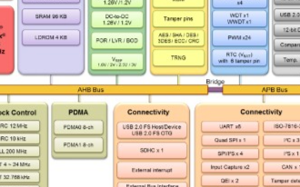
新唐科技 NuMicro M263KIAAE 是新一代 32 位低功耗微控制器产品,基于 Arm Cortex-M23 内核,支持 Armv8-M 指令集架构。其工作频率达 64 MHz,内嵌可支持
2020-01-13 10:40
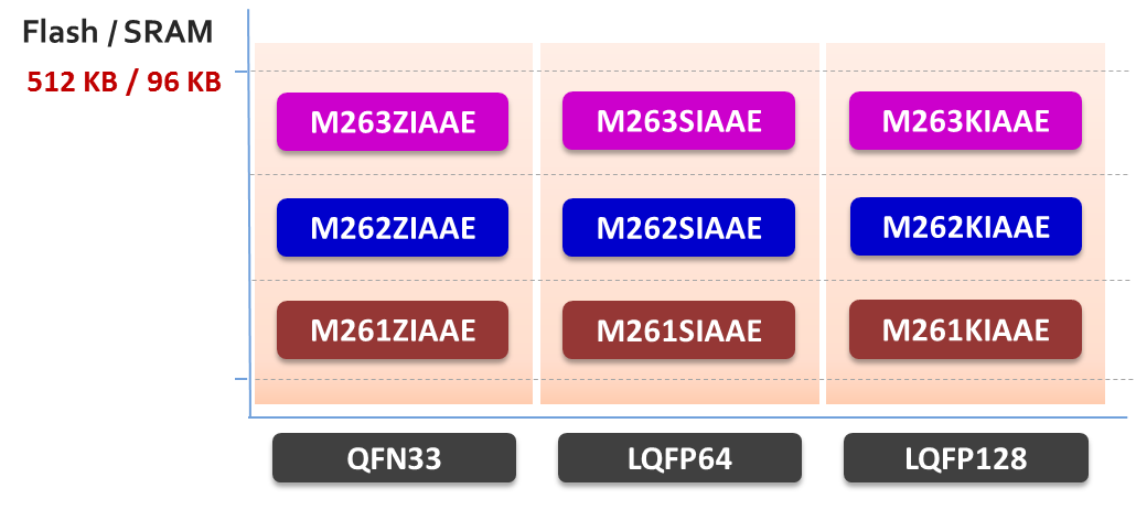
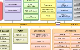
新唐科技 NuMicro® M261 / M262 / M263 系列是新一代 32 位低功耗微控制器产品,基于 Arm® Cortex®-M23 内核,支持 Armv
2019-11-19 09:36
电子发烧友网站提供《AM263x和AM263Px硬件设计指南.pdf》资料免费下载
2024-08-23 10:04