programming toolkit读取芯片的UID 因为读取接口无论是使用\"EReadAll\"还是\"EReadArea\"都必须指定
2024-05-11 08:11
三星宣布将开发手持式装置用的RFID(radio frequency identification)读取芯片,能让使用者透过手机得知产品和服务信息,但三星并未透露产品何时上市。 三星指出,RFID
2019-07-04 07:26
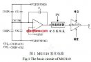
介绍了通用电容读取芯片 MS3110 的内部结构、基本原理及其使用方法,提出了采用单片机实现片内EEPROM 编程的方法,并给出了读写控制框图。以梳齿式硅微传感器为敏感元件,采用滞后
2011-07-16 11:47
/**************************************************************************** * @filemain.c * @versionV3.00 * $Revision: 9 $ * $Date: 15/07/02 11:18a $ * @brief *Demonstrate how to change system clock to different PLL frequency and output system clock from CLKO pin. * * @note * Copyright (C) 2014~2015 Nuvoton Technology Corp. All rights reserved. * ******************************************************************************/ #include #include \"NUC123.h\" #define HCLK_CLOCK 72000000 #define SIGNATURE 0x125ab234 #define FLAG_ADDR 0x20000FFC /*---------------------------------------------------------------------------------------------------------*/ /* Define functions prototype*/ /*---------------------------------------------------------------------------------------------------------*/ int32_t main(void); /*---------------------------------------------------------------------------------------------------------*/ /*Brown Out Detector IRQ Handler */ /*---------------------------------------------------------------------------------------------------------*/ void BOD_IRQHandler(void) { /* Clear BOD Interrupt Flag */ SYS_CLEAR_BOD_INT_FLAG(); printf(\"Brown Out is Detected\\n\"); } /*---------------------------------------------------------------------------------------------------------*/ /*Simple calculation test function*/ /*---------------------------------------------------------------------------------------------------------*/ #define PI_NUM256 int32_t f[PI_NUM + 1]; uint32_t piTbl[19] = { 3141, 5926, 5358, 9793, 2384, 6264, 3383, 2795, 288, 4197, 1693, 9937, 5105, 8209, 7494, 4592, 3078, 1640, 6284 }; int32_t piResult[19]; int32_t pi(void) { int32_t i, i32Err; int32_t a = 10000, b = 0, c = PI_NUM, d = 0, e = 0, g = 0; for(; b - c;) f[b++] = a / 5; i = 0; for(; d = 0, g = c * 2; c -= 14,/*printf(\"%.4d\\n\",e+d/a),*/ piResult[i++] = e + d / a, e = d % a) { if(i == 19) break; for(b = c; d += f * a, f = d % --g, d /= g--, --b; d *= b); } i32Err = 0; for(i = 0; i < 19; i++) { if(piTbl != piResult) i32Err = -1; } return i32Err; } void Delay(uint32_t x) { int32_t i; for(i = 0; i < x; i++) { __NOP(); __NOP(); } } uint32_t g_au32PllSetting[] = { CLK_PLLCON_PLL_SRC_HXT | CLK_PLLCON_NR(3) | CLK_PLLCON_NF(25) | CLK_PLLCON_NO_4,/* PLL = 25MHz */ CLK_PLLCON_PLL_SRC_HXT | CLK_PLLCON_NR(3) | CLK_PLLCON_NF(29) | CLK_PLLCON_NO_4,/* PLL = 29MHz */ CLK_PLLCON_PLL_SRC_HXT | CLK_PLLCON_NR(3) | CLK_PLLCON_NF(33) | CLK_PLLCON_NO_4,/* PLL = 33MHz */ CLK_PLLCON_PLL_SRC_HXT | CLK_PLLCON_NR(3) | CLK_PLLCON_NF(37) | CLK_PLLCON_NO_4,/* PLL = 37MHz */ CLK_PLLCON_PLL_SRC_HXT | CLK_PLLCON_NR(3) | CLK_PLLCON_NF(41) | CLK_PLLCON_NO_4,/* PLL = 41MHz */ CLK_PLLCON_PLL_SRC_HXT | CLK_PLLCON_NR(3) | CLK_PLLCON_NF(45) | CLK_PLLCON_NO_4,/* PLL = 45MHz */ CLK_PLLCON_PLL_SRC_HXT | CLK_PLLCON_NR(3) | CLK_PLLCON_NF(49) | CLK_PLLCON_NO_4/* PLL = 49MHz */ }; void SYS_PLL_Test(void) { int32_ti; /*---------------------------------------------------------------------------------------------------------*/ /* PLL clock configuration test*/ /*---------------------------------------------------------------------------------------------------------*/ printf(\"\\n-------------------------[ Test PLL ]-----------------------------\\n\"); for(i = 0; i < sizeof(g_au32PllSetting) / sizeof(g_au32PllSetting[0]) ; i++) { /* Switch HCLK clock source to HXT and HCLK source divide 1 */ CLK_SetHCLK(CLK_CLKSEL0_HCLK_S_HXT, CLK_CLKDIV_HCLK(1)); /* Set PLL to power down mode and PLL_STB bit in CLKSTATUS register will be cleared by hardware. */ CLK_DisablePLL(); /* Set PLL frequency */ CLK->PLLCON = g_au32PllSetting; /* Waiting for PLL clock ready */ CLK_WaitClockReady(CLK_CLKSTATUS_PLL_STB_Msk); /* Switch HCLK clock source to PLL */ CLK_SetHCLK(CLK_CLKSEL0_HCLK_S_PLL, CLK_CLKDIV_HCLK(1)); printf(\"Change system clock to %d Hz ...................... \", SystemCoreClock); /* Output selected clock to CKO, CKO Clock = HCLK / 2^(1 + 1) */ CLK_EnableCKO(CLK_CLKSEL2_FRQDIV_S_HCLK, 1, 0); /* The delay loop is used to check if the CPU speed is increasing */ Delay(0x400000); if(pi()) { printf(\"[FAIL]\\n\"); } else { printf(\"[OK]\\n\"); } /* Disable CKO clock */ CLK_DisableCKO(); } } void SYS_Init(void) { /*---------------------------------------------------------------------------------------------------------*/ /* Init System Clock*/ /*---------------------------------------------------------------------------------------------------------*/ /* Enable XT1_OUT(PF0) and XT1_IN(PF1) */ SYS->GPF_MFP |= SYS_GPF_MFP_PF0_XT1_OUT | SYS_GPF_MFP_PF1_XT1_IN; /* Enable Internal RC 22.1184MHz clock */ CLK_EnableXtalRC(CLK_PWRCON_OSC22M_EN_Msk); /* Waiting for Internal RC clock ready */ CLK_WaitClockReady(CLK_CLKSTATUS_OSC22M_STB_Msk); /* Switch HCLK clock source to Internal RC and HCLK source divide 1 */ CLK_SetHCLK(CLK_CLKSEL0_HCLK_S_HIRC, CLK_CLKDIV_HCLK(1)); /* Enable external XTAL 12MHz clock */ CLK_EnableXtalRC(CLK_PWRCON_XTL12M_EN_Msk); /* Waiting for external XTAL clock ready */ CLK_WaitClockReady(CLK_CLKSTATUS_XTL12M_STB_Msk); /* Set core clock as HCLK_CLOCK */ CLK_SetCoreClock(HCLK_CLOCK); /* Enable UART module clock */ CLK_EnableModuleClock(UART0_MODULE); /* Select UART module clock source */ CLK_SetModuleClock(UART0_MODULE, CLK_CLKSEL1_UART_S_HXT, CLK_CLKDIV_UART(1)); /*---------------------------------------------------------------------------------------------------------*/ /* Init I/O Multi-function*/ /*---------------------------------------------------------------------------------------------------------*/ /* Set GPB multi-function pins for UART0 RXD(PB.0) and TXD(PB.1) */ SYS->GPB_MFP &= ~(SYS_GPB_MFP_PB0_Msk | SYS_GPB_MFP_PB1_Msk); SYS->GPB_MFP |= (SYS_GPB_MFP_PB0_UART0_RXD | SYS_GPB_MFP_PB1_UART0_TXD); /* Set GPC multi-function pin for Clock Output(PC.13) */ SYS->GPC_MFP &= ~SYS_GPC_MFP_PC13_Msk; SYS->ALT_MFP &= ~SYS_ALT_MFP_PC13_Msk; SYS->GPC_MFP |= SYS_GPC_MFP_PC13_CLKO; SYS->ALT_MFP |= SYS_ALT_MFP_PC13_CLKO; } void UART0_Init() { /*---------------------------------------------------------------------------------------------------------*/ /* Init UART*/ /*---------------------------------------------------------------------------------------------------------*/ /* Reset UART0 module */ SYS_ResetModule(UART0_RST); /* Configure UART0 and set UART0 Baudrate */ UART_Open(UART0, 115200); } /*---------------------------------------------------------------------------------------------------------*/ /* MAIN function */ /*---------------------------------------------------------------------------------------------------------*/ int32_t main(void) { uint32_t u32data; /* In end of main function, program issued CPU reset and write-protection will be disabled. */ if(SYS_IsRegLocked() == 0) SYS_LockReg(); /* Unlock protected registers */ SYS_UnlockReg(); /* Init System, peripheral clock and multi-function I/O */ SYS_Init(); /* Lock protected registers */ SYS_LockReg(); /* Init UART0 for printf */ UART0_Init(); printf(\"\\n\\nCPU @ %dHz\\n\", SystemCoreClock); /* This sample code will show some function about system manager controller and clock controller: 1. Read PDID 2. Get and clear reset source 3. Setting about BOD 4. Change system clock depended on different PLL settings 5. Output system clock from CKO pin, and the output frequency = system clock / 4 */ printf(\"+----------------------------------------+\\n\"); printf(\"| NUC123 System Driver Sample Code |\\n\"); printf(\"+----------------------------------------+\\n\"); if(M32(FLAG_ADDR) == SIGNATURE) { printf(\"CPU Reset success!\\n\"); M32(FLAG_ADDR) = 0; printf(\"Press any key to continue ...\\n\"); getchar(); } /*---------------------------------------------------------------------------------------------------------*/ /* Misc system function test */ /*---------------------------------------------------------------------------------------------------------*/ /* Read Part Device ID */ printf(\"Product ID 0x%x\\n\", SYS_ReadPDID()); /* Get reset source from last operation */ u32data = SYS_GetResetSrc(); printf(\"Reset Source 0x%x\\n\", u32data); /* Clear reset source */ SYS_ClearResetSrc(u32data); /* Unlock protected registers for Brown-Out Detector settings */ SYS_UnlockReg(); /* Check if the write-protected registers are unlocked before BOD setting and CPU Reset */ if(SYS_IsRegLocked() == 0) { printf(\"Protected Address is Unlocked\\n\"); } /* Enable Brown-Out Detector, and set Brown-Out Detector voltage 2.7V */ SYS_EnableBOD(SYS_BODCR_BOD_INTERRUPT_EN, SYS_BODCR_BOD_VL_2_7V); /* Enable BOD IRQ */ NVIC_EnableIRQ(BOD_IRQn); /* Enable Low Voltage Reset function */ SYS_ENABLE_LVR(); /* Run PLL Test */ SYS_PLL_Test(); /* Write a signature work to SRAM to check if it is reset by software */ M32(FLAG_ADDR) = SIGNATURE; printf(\"\\n\\n>>> Reset CPU <<<\\n\"); /* Waiting for message send out */ UART_WAIT_TX_EMPTY(UART0); /* Switch HCLK clock source to Internal RC 22.1184MHz clock and HCLK source divide 1 */ CLK_SetHCLK(CLK_CLKSEL0_HCLK_S_HIRC, CLK_CLKDIV_HCLK(1)); /* Set PLL to Power down mode and HW will also clear PLL_STB bit in CLKSTATUS register */ CLK_DisablePLL(); /* Reset CPU */ SYS_ResetCPU(); }
2023-06-14 09:11
请问trace32如何读取芯片数据到文件?
2021-09-30 07:15
HMC1197读取芯片ID失败(Reg00h)串口一直显示为00 FF FF FF。而且用示波器检测,发现时钟信号的电压低于1V。read部分的程序已经在附件中。希望有经验的朋友能给予指导。附件read1197.c.zip633 字节
2018-08-03 06:46
在很多场合下,想要读取芯片中的代码,保存下来。方便后续使用。方法如下:Data.save.S3record filename-s3.mot
2021-07-27 08:15
本人用STM32F103c8t6打了一块板子,但是拿到手焊好元器件准备调试的时候ST LINK Utility读不出芯片信息如图 电路图如下 电路板焊好后 说明:启动模式都试过 BOOT0
2020-03-17 03:19
9月26日,中国邮政发行《第40届全国最佳邮票评选纪念》邮票纪念张,这是中国首枚NFC芯片邮票。该邮票在传统印刷工艺中植入NFC芯片,集邮者可通过中国邮政App读取芯片
2020-10-10 11:09

每一个STM32单片机出厂的时候都有全球唯一的ID,当在数据安全性比较高的地方,需要对每一个接入系统的芯片进行身份验证,那么这个芯片自身的ID号就可以作为它的身份信息。产品唯一的身份标识非常适合
2021-11-26 17:51